It is accessed via the "Scan" button on the examination screen. Since all data are recorded, the patient record and the examination record must be entered. In the latter, "Diplopia field" must be selected in the type of examination.
It is displayed in full screen.
It has 4 well-defined areas:
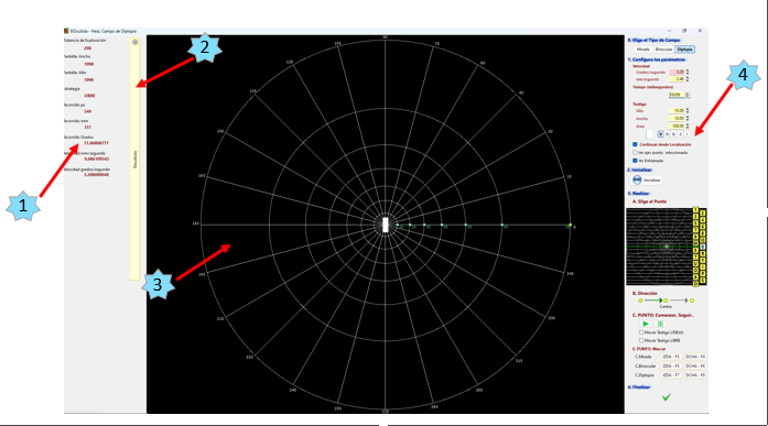
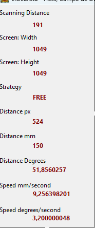
1. Information Area (1).
Located on the left and at the top, it shows the scanning distance, the width and height of the screen and the type of strategy, in this case, FREE, the travel in pixels, millimetres and degrees and the speed of the token in both degrees/second and mm/second.
2. Drop-down results panel (2).
It is initially minimised and can be accessed by simply pressing it.
If the left-hand side of the panel is pressed, it closes or opens depending on its previous location.
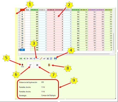
It has the following elements:
· Push button to open and close the area (1).
· List of the points explored and their answers (2).
· Navigator (3).
Allows scrolling through the different responses, as well as editing and selective deletion. If a position has not been performed correctly, it can be deleted here and repeated.
· Button "Initialise" (4).
Allows you to delete all the answers entered in the list. You must perform the whole scan again.
· Button "Save Data" (5).
Don't forget to press it.
If you exit the screen before saving, you will lose all the data of the scan.
In addition, it starts the process of calculating the surface of the answer polygon.
· Accept scan and exit the screen" button (6).
Once the scan is done and the data is saved, press this button to exit. DO NOT exit by closing the window with the Windows menu.
· Cancel" button (7).
To exit without saving anything.
· Button "Exit" (8).
To close the screen and return to the list of scans.
· Informative Panel (9).
Here we can see the data of the scan performed: scanning distance, width and height of the screen used, strategy and surface of the polygon of answers.
3. Actual scanning screen (3).
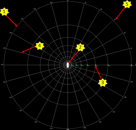
In it we have:
· Lattice composed of circles (1) at 10º, 20º, 30º, 40º, 40º, 50º, 60º and 70º, green dots (3) at the radius of 0º at the intersections with the circles, 12 diameters (4) arranged at 15º, 30º, 45º, 60º, 75º, 90º, 105º, 120º, 135º, 150º, 165º and 180º, degrees (5) of each line, yellow central dot and dots indicating the line that the movement of the tell-tale will follow.
· Token (2).
Rounded or rectangular in shape.
The lattice can be visible or not.
The token can move automatically or freely across the screen.
4. Command area and scan control (4).
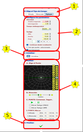
It is divided into 4 zones organised in such a way that they follow the normal order of exploration:
· Selector "Diplopia Field Type". (1).
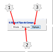
Here you must choose the type(s) of scanning you wish to do:
- Field of View (1) (its response points, selectors and grid lines in Green).
- Binocular Field (2) (its response points, selectors and grid lines in Blue).
- Diplopia Field (3) (Its response points, selectors and framing lines in Red).
· Test parameters configurator (2).
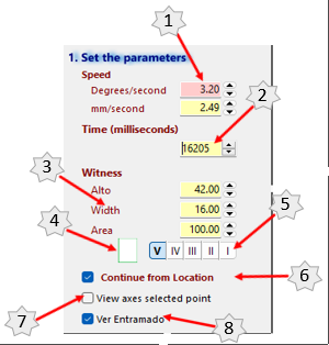
Allows the following to be set:
- Speed of token movement (1) in degrees/second or millimetres/second. The usual speed is 3.2 degrees per second.
- The time in milliseconds (2) for the bore to travel the distance between 2 points. It is automatically adjusted to the length of the line to be scanned so that the speed is the same for all scanned lines.
- The size of the token (3), being able to change its height and width if it is rectangular or its radius if it is rounded. If the area is changed, the above data is automatically adjusted.
- The shape of the token (4): rectangular or rounded.
- Goldmann Customary size selector (5), have been included for compatibility. The size is adjusted to the scanning distance.
- Selector "Continue Test from Current Core Location" (6).
Selector "View Axes Selected Point" (7).
- View Lattice" selector (8).
· Test resetter or initialiser (3).

Changes all test parameters to their default value in order to start the test. Deletes all data from an already started scan in order to start it again.
.
· Control area where the test is to be carried out (4).
This is the area where all the commands for scanning each line and performing the test are located. Its layout follows the scan course: 1st a scan line is chosen, 2nd the token is moved and 3rd the locations are marked according to the type of test. As they are horizontal scan lines, their left and right location must be marked.
The following command buttons are available:
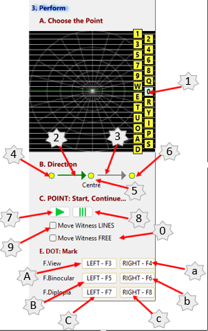
- Line selector (1).
The scanning is performed following a pattern of horizontal lines in order to map the chosen field.
There are 22 lines available. Each one has its associated key, so that once the test has started, it is sufficient to press the chosen key and the associated line is selected.
- Direction selector for the movement of the tell-tale towards the centre (2).
Normally, the tell-tale is moved from the periphery towards the centre, although the desired strategy may be followed.
- Direction selector for outward movement of the telltale (3).
- Position the token on the left edge of the line to be scanned (4).
- Position the token at the centre of the line to be scanned (5).
- Position the token at the right edge of the line to be scanned (6).
- Start or continue the movement of the core (7).
This button must be pressed to start the movement and start the test. When the test is paused and we wish to restart the test, this button must be pressed.
It must be taken into account that the selector "Move the token from Location" if we want the movement to restart at the place where we stopped it, otherwise it returns to the beginning of the line.
- Stop the movement of the token (8).
- Selector "Move the token LINES" (9).
To move the token manually along the currently selected line, mark this selector, place the mouse over the token, press the left mouse button and without releasing it move the token to the desired position, once in the desired place release the left mouse button.
- Selector "Move Token FREE" (0).
Allows the token to move freely around the screen.
- Button Marking the left edge of the Look Field. Associated key F3 (A).
- Button Marks the right edge of the Field of View. Associated key F4 (a).
- Button Marks the left edge of the Binocular Field of View. Associated key F5 (B).
- Button Marks the right edge of the Binocular Field. Associated key F6 (b).
- Mark the left edge of the Diplopia Field. Associated key F7 (C).
- Mark the right edge of the Diplopia Field. Associated key F8 (c).
· End of the test (5).

The data drop-down panel opens, allowing data to be queried, validated and saved.
